 |
SPECIFICATIONS
Controls and
Connections
Basic Programming
Procedures
Owners Manual

Factory
Service Manual 
Page
1-1 to 5-4
Page
7-1 to 7-13
Page
8-1 to 8-13
Page
10-1 to 11-8
Service
Notes
CPU
faults  (Courtesy of Rick
Jackson Euro Radio Co)
Paper
that explains how the Pass regulator works. 
ALIGNMENT
PROCEDURES
PLL
Alignment
Transmitter Alignment
Receiver
Alignment
SEMICONDUCTOR
INFORMATION
Transistors
Voltage Chart
DIAGRAMS
Main
PCB Schematic Diagram (Courtesy of Rick Jackson)

CPU
PCB Schematic Diagram (Courtesy of Rick Jackson) 
RCI-2950
Inter-connection Diagram
Chassis
Exploded View Drawing
PCB Layouts and
Parts
Main
PCB Layout (EPT295013Z)
LCD
PCB (EPT295021Z)
CPU PCB
(EPT295043Z)
MIC UP/DW
(EPT295080Z)
MIC
Jack PCB (EPT295070Z)
SWR PCB
(EPT360040Z)
VR (A) PCB
RF/MIC VOL/SQ (EPT295050Z)
VR (B) PCB
RF/CAL (EPT295060Z)
CH / Switch
PCB (EPT295090A)
MODE PCB
(EPT295090Z)
Push
Button Switch PCB (EPT295031Z)
Chassis, Miscellaneous
& Mechanical Parts
Miscellaneous
& Mechanical Parts

|
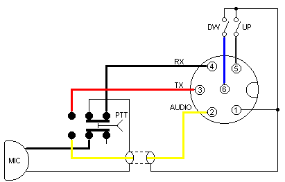
Mic Wiring Info
Stock Mic Wiring
1. Ground
Shield
2. Audio Yellow
3. Transmit Red
4. Receive Black
5. CH. Up White
6. CH. Down Blue
Turner 4-Wire
MIC. Wiring
1. Ground Shield
2. Audio White
3. Transmit Black
4. Receive N/C
5. CH. UP N/C
6. CH. Down N/C
Turner 6-Wire
MIC. Wiring
1. Ground Shield & Red
2. Audio White
3. Transmit Blue
4. Receive N/C
5. CH. UP N/C
6. CH. Down N/C
Astatic 4-Wire
MIC. Wiring
1. Ground Shield
2. Audio White
3. Transmit Red
4. Receive N/C
5. CH. UP N/C
6. CH. Down N/C
Astatic 6-Wire
MIC. Wiring
1. Ground Shield & Blue
2. Audio White
3. Transmit Red
4. Receive N/C
5. CH. UP N/C
6. CH. Down N/C
|

