|
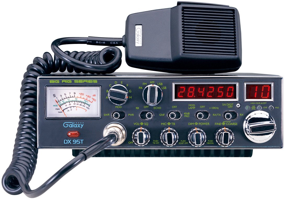
RADIO
MODIFICATIONS
DX95T
Frequency Conversion
Channel
Chart (After Modification)
Extended
10-Meter Frequency Conversion (28.000 - 29.655MHz
ALIGNMENT
PROCEDURES
PLL Alignment
Transmitter Alignment
Receiver Alignment
Alignment Locations
VR
PCB Alignment Locations
SEMICONDUCTOR
INFORMATION
Semiconductor
Datasheets
DIAGRAMS
Schematic
Diagram Main  (May 21, 2003)
RF
Amp Schematic (EPA010011D)
(Nov. 06, 2001)
EL
Driver Schematic (EPT91V130Z)
Control
wiring
(May 08, 2003)
PCB Layouts and
Parts
Main PCB (EPT690010C)
VCO
PCB (EPF000210Z)
RF AMP
PCB (EPA010011D) Early Production
RF AMP PCB
(EPA010012D) Current Production
Amp Feed Back
PCB (EPA010030Z)
Dimmer PCB
(EPT091V41A)
EL Driver
PCB (EPT91V130Z)
ECHO PCB (EPT0SSB51J)
VR PCB (EPT091V93Z)
Display / Switch
PCB (EPT091V23Z)
Channel Selector
/ Frequency Counter PCB (EPT091V34Z)
SWR
PCB (EPA010020B)
ANF/GNF
PCB (EPT009830Z)
MOD LED PCB
(EPT91V100Z)
LED PCB
(EPT91V120Z)
Chassis, Miscellaneous
& Mechanical Parts
Chassis
& Mechanical
Mic Wiring Diagram
|
Stock
1- Shield
(Ground)
2- Yellow (Audio)
3- Red (Transmit)
4- White (Receive)
Astatic (4
wire)
1- Shield
2- White
3- Red
4- Black
Astatic (6
wire)
1- Shield & Blue
2- White
3- Red
4- Black
Yellow NC
Daiwa EM-500
Cobra CA Series
1- Shield & Black
2- Red
3- White
4- Blue
Galaxy DC-521S
(4 wire)
1- Shield
2- Yellow
3- Red
4- Black
Galaxy CB-660EI
1- Shield & Black
2- White
3- Red
4- Blue
Sadelta
1- Shield
2- White
3- Brown
4- Green
Turner
1- Shield & Red
2- White
3- Blue
4- Black
Yellow NC
|