What are the EKL Companion Parts?
The EKL ENXXX's have
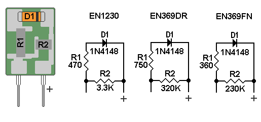
the following on a ceramic substrate.
Two thick film resistors One diode (SMT)
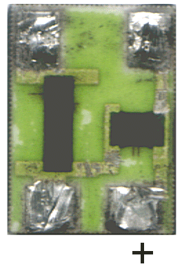
If you look close at the picture that a member of the forum posted at
the right you can see the laser trim marks on the resistors.
The the people that want to know what the heck is a laser trim mark. When
thick film metal alloy is deposited on a substrate the deposit target
value is always higher than the desired value, you then take a laser to
trim the value
of the metal alloy deposit to the desired value.
He said the epoxy is very easy to remove so take one apart and have a look for yourself.
Here is a schematic of the EKL companion parts.

Schematic of the EKL ENXXX's
The following was posted on the forum from a member of the site.
Just for the record
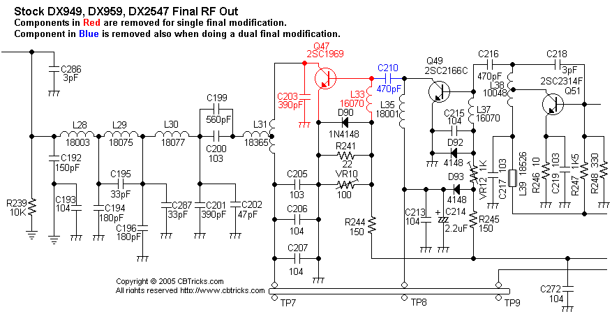
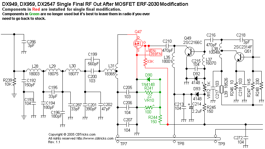
I thought I'd try the single mosfet in a DX33HML using the directions
provided.
In all honesty I have to admit it worked rather well.
I posted some wattage readings below with notes.
2SC1969:
25.615 - deadkey = 8.5 watts - 28 watts peak
26.965 - deadkey = 9.0 watts - 31 watts peak
27.865 - deadkey = 9.0 watts - 30 watts peak
ERF2030:
25.615 - deadkey = 8.3 watts - 38 watts peak
26.965 - deadkey = 9.5 watts - 43 watts peak
27.865 - deadkey = 9.4 watts - 40 watts peak
Notes:
Peak power readings on IFR1200 Communications test set.
No modulation limiters removed.
Full modulation with no flat topping.
Current draw same on both devices.
68pf cap not recommend (causes less output)
Do not remove L33 slug (required to balance power on upper and lower bands.)
ERF2030 has slight impedance mismatch on the output. (not bad)
The number one Question on the EKL MOSFET Application Notes.
There has been questions
on where is R285 in the Galaxy EKL MOSFET Application
Notes.
EKL must have just tested this on a EPT360014C board..
First we start
with EPT3600-14B (Dip IC9)
There is
no R285 on the EPT3600-14B.
The resistor is on the copper side on IC9 Pins 10&12 to gnd and in
the prints is Ref. as R281 in the schematics.
Only dual final radios have this resistor (But not always Ranger put it on some single final models also.)
See bottom layout
right side for Location of resistor (it marked as 1K and I need to add
a ref#).
http://www.cbtricks.com/radios/galaxy/dx44v/graphics/44v_3600-14b_bot_color.gif
See this schematic
(zoon in to IC9 to see R281 Pins 10&12 to gnd)
http://www.cbtricks.com/radios/galaxy/dx73v/graphics/Dx-73v_sch.pdf
Now the EPT360014C
(SMT IC9)
On a EPT3600-14C R285 is in Location C1 (See the EPT3600-14C Top layout).
http://www.cbtricks.com/radios/galaxy/dx44v/graphics/44v_3600-14c_top.gif
This 1K resistor from the factory and go's from IC9 Pins 9&11 to gnd.
See this schematic
(zoon in to IC9 to see R285)
http://www.cbtricks.com/radios/galaxy/dx44v/graphics/dx44v_main_sch_14c.pdf
Now print the following
datasheets that explains the function for these pins is stroll down to
S042P Mixer (Dip) and TDA6130-5X4 Mixer (SMD).
http://www.cbtricks.com/radios/galaxy/datasheets/ic_index.htm
R281 (14B) and R285 (14C) have the same function in the circuit.


