Along with some improvements to it's life.

To begin, I'm assuming you've taken the covers off and have the main board exposed...
Locate Final and Driver, did you ever wonder why holes are still in the board - with no parts?
This is what differentiates this Radio from the other predecessors in this line of radios based on this chassis. To get varying levels of performance, some parts are omitted to allow this chassis to be used in the USA and exported to other countries that follow FCC guidlines.
And some parts can be replaced or put in, when the country is following ITU regs, or has no limits on power capacity or other restrictions.
This radio, is not a Galaxy by any means. It's a unique radio.
How were these mods, or part differentiations, discovered?
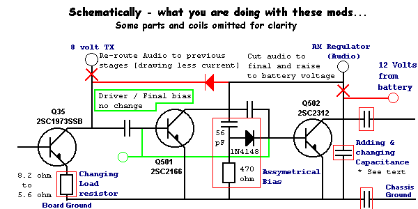
Mostly due to experiments. One mod in particular is soley dedicated to the HIGH-End models like the 640e and 810e chassis designs. These actually improve modulation by offering Assyemtrical Modulation - by means of RF-Clipping and rectification to raise or lower RF drive from the Driver to the Final [the RED resistor, Blue diode, and Cyan cap locations] when the modulation is applied to the driver [*].
This enhances audio, and lessening the likelyhood of generating Harmonics that can seriously degrade performance and also get a lot of neighbors upset when not implemented.
Other things that people may not know about.
Overheating!
Yes, it's sad to admit but this radio chassis does have some serious drawbacks...
This is alleviated somewhat by removing the Final from the AM Regulator due to the current demand the Final placed on the AM Regulator - a 2SA1012 Audio Amp/Switch, and wiring the Final directly to the radios power supply filter.
Although the 2SA1012 is capable of handling 5 amps, the AM Modulation requirement placed the transistor in the Linear range of operation and forced the transistor to produce excessive heat, which caused the failure due to thermal runaway. That, along with a small chassis heat sink rear panel, there simply isn't enough metal to pull and dissapate heat the Driver, Final, and the AM Regulator/Modulator placed on this single panel.
A little known method to obtain a heat-sink for this type of problem...
Heat is still a problem with this radio - and if you haven't already noticed, there is a long "U;"-shaped bracket that is a heat sink for the Final and Driver. This metal bracket can be inverted allowing the flat surface of it's "U;" shape to transfer heat away into another body panel - that being the speaker panel.
BE SURE TO BLOW OUT ALL METAL SHAVINGS CAUGHT INSIDE AND CHECK FOR
SHORTS!
Let's see that photo...I will remind you that this has been dissassembled from a PC122 - NOT A PC122XL chassis! These two are similar, but read on!
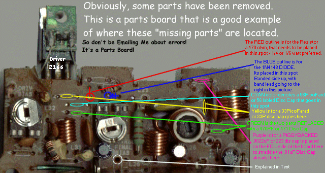
The above should be self-explanatory, except for the white circled area.
The circled area is part of the Mirror board assembly. This board shorted 3 jumper test points together in the stock radio. The center test point or clip needs to be removed, by unsoldering it.
This jumper mod puts the Final on a direct line to the power supply and removing the center jumper but keeping the other two, allows for modulation to be sent to the Driver.
The Final then simply acts like a Class-AB biased Modulator. To check and adjust Bias on the Final, simply place your VOM red lead probe tip to the left side on the Varistor MV-1Y and Black or Ground lead tip to BOARD Ground - or convenient Metal Tank Coil Can shield. Adjust the Final Bias trimmer pot to show 0.67 volts when the radio is in USB mode with no modulation and you're all set. It will run cooler for a longer period of time and sound better when carrier level exceeds 4 watts.
The final conversion of this deals with the Pre-Driver or Q35. The original design can be left intact if you so desire - but you do want to increase the RF drive on the Driver to reduce chances of overheating or splatter if you give this radio a lot of modulation.
The easiest way to do this is to use a diode, a 1N4001 or a 1N4148 with at least a 1A rating and solder it to the 8 volt line feeding it.
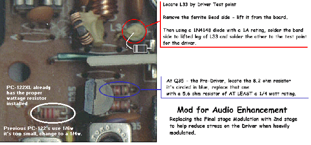
In order to maintain audio quality plus performance, after this jumper mod is done, a re-tweak of the Finals' Tank-Coil, the white form with slug in photo, should be adjusted to offer MAXIMUM Audio Drive and should never be adjusted for Carrier Power.
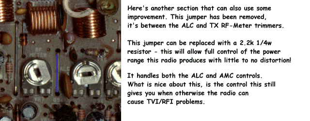
After you've done the above mods, you'll still need to get after the power level control. This radio still thinks that it's a 4-watt radio. The AMC and ALC sense control is thru a jumper just past the final output tank. This jumper can be removed and replaced with a 2.2k resistor. The location of the jumper is shown below.
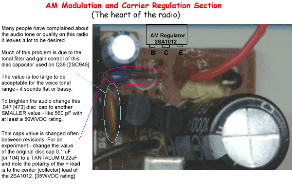
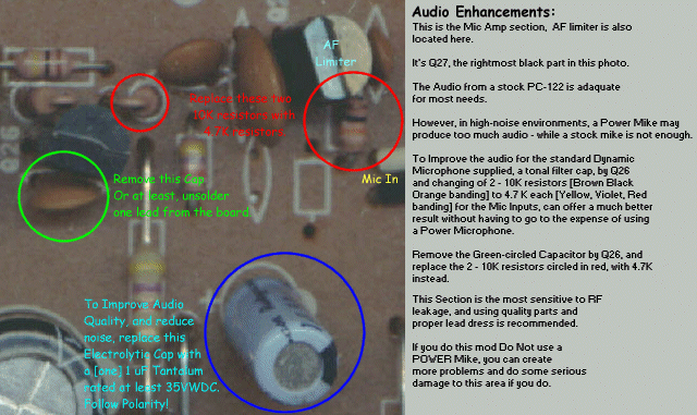
Some interesting and useful audio filter mods and a volume increase mod can also help make this radio sound good.
The moment you've been waiting for...The Clarifier mod.
Please pay attention to details in the below picure - it's a biggie and will take some time to load. Study it and do the mod, you're all done.
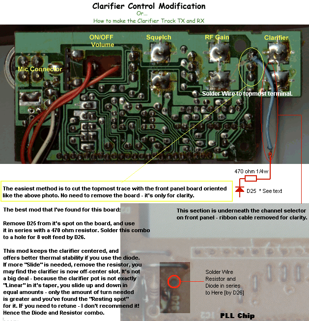
You may also find a 4pF cap soldered across the leads of the 10.2417 Xtal by
D25. It's on the foil side, once this mod is done - you can remove it. As a
word of warning though
It does change the tuning of this circuit so "Center Slot"
will change and you will get a lot more slide - at a cost of stability!
Have fun...and remember...
For Educational Purposes only!
© 1997 by Andrew Cody - All rights reserved.